Chiller Plant - Case study
Chiller plant
The chilled water system consists of three 800-ton electric centrifugal chillers (Chiller 1, 2, 3)
and associated pumps. The chilled water system is a variable primary flow design.
challenge
Initial review of past events and trend logs indicated erratic behavior of the Chiller Plant, multiple failures,
and difficulty of control, especially during start/stop.
Outcome
Upon completion of this project, all primary issues had been resolved, and the equipment and systems were controlling and
operating well, energy consumption and the associated PUE were reduced.
Problems Encountered
The plant had difficulty maintaining temperature control
and energy use and PUE values were high
Multiple issues were found to be contributing to both the chilled water system and condenser water systems instability,
failures, and increased energy consumption. Extensive control programming and equipment modifications were required to
be implemented and functionally tested for verification.
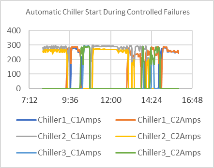
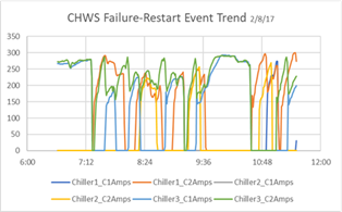
Unique hydraulic conditions, encountered primarily during Chiller staging were causing uncontrolled Chiller failures. Excessive
CHWP, CWP, and CT equipment operation was causing unnecessary energy use, equipment wear and reduced operational flexibility. Chiller
settings, wiring and control modifications were made to improve response time and temperature control. Extensive control programming
and equipment modifications were implemented and tested.
Developing the Strategy
An initial testing plan, intended to model the Chiller Plant under various conditions based on the SOO,
was written, and implemented. Subsequent additional investigation and testing was required to achieve the
required performance of the Chiller Plant equipment and systems.
The mechanical equipment and control systems were operated over a range of conditions, in various types of
unit configurations and multiple types of failure events were tested.
The chilled water pumps are variable speed, controlled by the BMS to
maintain adequate flow through the chillers and to the CRAH unit loads. Pressure differential (CHWS<>CHWR) is maintained across
the cooling loop for the delivery of chilled water to the cooling units (CRAH’s) in the data center space and electric rooms.
The chilled water (CHW) flow requirement for the chillers will be maintained by a minimum pump speed and the control of two bypass
valves (Bypass Valves CV-1 and CV-2) in the chilled water mains. The Bypass valves will be controlled so that the minimum flow is
always met for each operating chiller evaporator.
results
Chiller settings, wiring and control modifications were made to improve response time and temperature control. Extensive control
programming and equipment modifications were implemented and tested.